


Hold off on this mod. Looks like there is an issue that makes it fail after about an hour.
The forum appears to unhelpfully be adding advertisements to this post... There are no useful links in this post.
I picked up a spare factory Delphi charger from eBay for pretty cheap with the hope of converting it to a portable L2 charger. Here is how I did it.
Before I get started with the instructions, I disclaim any responsibility for damage or injury if you follow these instructions. It worked for me, but I can't promise it will work for you. There may be different PCB versions, etc. When working with 240V AC, there is always a risk of fire, injury, or death. This obviously voids any warranty and invalidates the UL listing.
That said, the charging current remains the same and the charger clearly is designed to allow this possibility.
To start, you'll need to gather a few tools and supplies
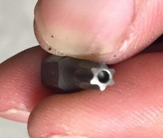
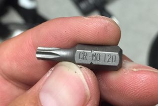
The first tool is a T20 Security Torx bit, which looks like this:
The second tool is a soldering iron, solder, and solder wick.
You will also need some new varistors. I used Panasonic ERZ-V20D511, purchased from Digi-Key as P/N P7235-ND for USD$2.04/ea. You will need 3 pieces.
I don't have a photo of the screws to remove, but it should be fairly obvious. You will need to remove 4 case screws, 5 PCB screws, and 2 cable clamp screws from the power inlet side. Here is a photo of the removed screws and clamp:
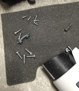
There may have been a different size Torx bit needed for the PCB screws, but if you have a standard torx bit set you should be fine. You could just use a security driver if needed.
Here are the markings on my PCB:
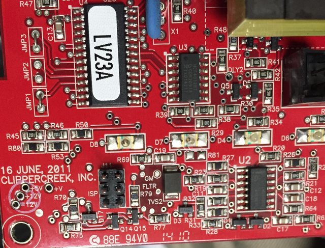
There are some jumpers next to the microcontroller (U4). I haven't experimented with these, but it is possible that they could control different functionality modes.
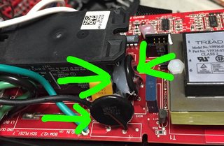
After removing the screws, desolder the 3 old varistors, marked here with green arrows (one is a bit hidden under the relay flange in this photo):
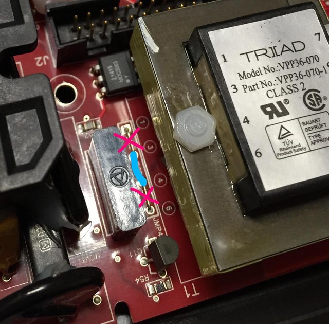
Next, we need to rewire the transformer for 220/240V operation. This is done by placing the primary windings in series instead of parallel.
Remove the jumper links from connections 1-3 and 4-6. Replace with a jumper on 3-4. Here is a marked up photo showing the removed jumpers in pink and the new jumper in blue:
Next, install the 3 new varistors and close up the unit by reinstalling all of the screws.
Finally, mark the unit for 220/240V use and test it out. You may want to replace the plug, but it isn't essential. You could instead use an adapter cable.
This will charge at roughly double the speed of the factory charger.
I tried plugging it in to a 110V outlet and it gives an error LED, so it shouldn't cause any damage if inadvertently connected. If you inadvertently connect the 110V unit to 220V, it will likely burn out the varistors or do something else bad.
I haven't tested it on 208V yet, but I'm guessing it should work.
The forum appears to unhelpfully be adding advertisements to this post... There are no useful links in this post.
I picked up a spare factory Delphi charger from eBay for pretty cheap with the hope of converting it to a portable L2 charger. Here is how I did it.
Before I get started with the instructions, I disclaim any responsibility for damage or injury if you follow these instructions. It worked for me, but I can't promise it will work for you. There may be different PCB versions, etc. When working with 240V AC, there is always a risk of fire, injury, or death. This obviously voids any warranty and invalidates the UL listing.
That said, the charging current remains the same and the charger clearly is designed to allow this possibility.
To start, you'll need to gather a few tools and supplies
The first tool is a T20 Security Torx bit, which looks like this:
The second tool is a soldering iron, solder, and solder wick.
You will also need some new varistors. I used Panasonic ERZ-V20D511, purchased from Digi-Key as P/N P7235-ND for USD$2.04/ea. You will need 3 pieces.
I don't have a photo of the screws to remove, but it should be fairly obvious. You will need to remove 4 case screws, 5 PCB screws, and 2 cable clamp screws from the power inlet side. Here is a photo of the removed screws and clamp:
There may have been a different size Torx bit needed for the PCB screws, but if you have a standard torx bit set you should be fine. You could just use a security driver if needed.
Here are the markings on my PCB:
There are some jumpers next to the microcontroller (U4). I haven't experimented with these, but it is possible that they could control different functionality modes.
After removing the screws, desolder the 3 old varistors, marked here with green arrows (one is a bit hidden under the relay flange in this photo):
Next, we need to rewire the transformer for 220/240V operation. This is done by placing the primary windings in series instead of parallel.
Remove the jumper links from connections 1-3 and 4-6. Replace with a jumper on 3-4. Here is a marked up photo showing the removed jumpers in pink and the new jumper in blue:
Next, install the 3 new varistors and close up the unit by reinstalling all of the screws.
Finally, mark the unit for 220/240V use and test it out. You may want to replace the plug, but it isn't essential. You could instead use an adapter cable.
This will charge at roughly double the speed of the factory charger.
I tried plugging it in to a 110V outlet and it gives an error LED, so it shouldn't cause any damage if inadvertently connected. If you inadvertently connect the 110V unit to 220V, it will likely burn out the varistors or do something else bad.
I haven't tested it on 208V yet, but I'm guessing it should work.